
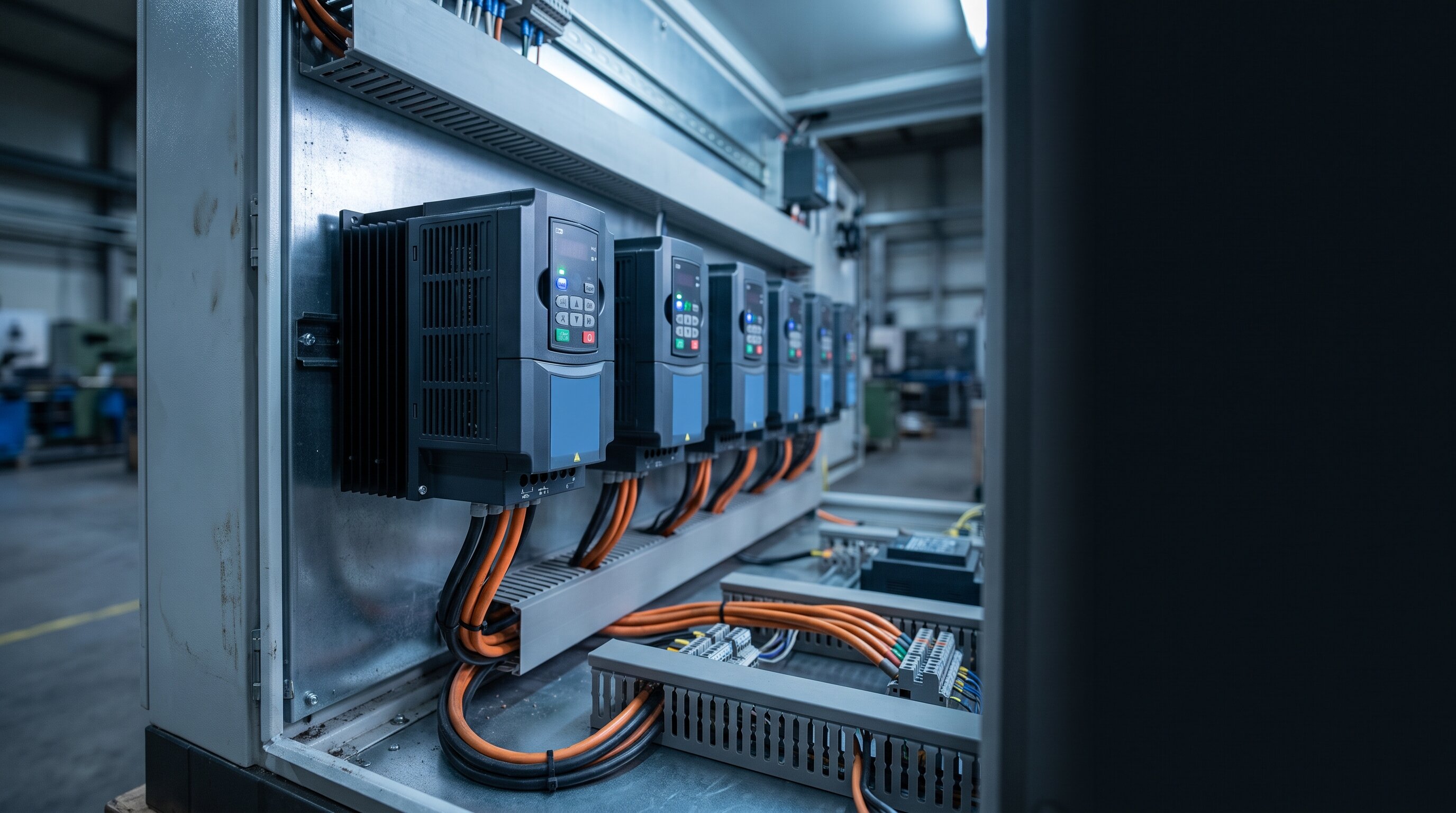
A variable frequency drive rarely fails without warning. It throws a fault code first, resets, runs for another week, then trips again—usually at the worst possible moment. That code on the keypad is the drive telling you exactly where it thinks the problem is, and learning to read it is the difference between a targeted fix and a parts-swapping guessing game.
The catch is that a VFD fault code describes a symptom, not a root cause. An overcurrent trip doesn't mean the drive is bad; it means the drive saw more current than it was willing to pass. The cause could be the motor, the cable, the load, the acceleration ramp, or the drive's own power section. This guide walks through the fault codes you'll actually see on a plant floor, what tends to be behind each one, and how to test a VFD safely when the code alone isn't enough.
Every major manufacturer—ABB, Allen-Bradley, Siemens, Yaskawa, Lenze, Mitsubishi, Emerson—uses its own numbering, so the exact string on the display varies. The underlying protection functions do not. Nearly every fault you'll encounter falls into one of six families: overvoltage, overcurrent, overtemperature, ground fault, undervoltage or input phase loss, and motor overload.
Before you touch anything, do two things. First, write down the exact fault code and the fault history—most drives store the last several faults with a time or run-hour stamp, and a pattern (always on startup, always on decel, always in the afternoon) is often more diagnostic than the code itself. Second, check whether the drive faults with the motor disconnected. A drive that runs clean with no motor attached is pointing you downstream.
An overvoltage fault means the DC bus climbed above its trip threshold. On a 480 V drive that bus normally sits around 650–680 V DC, and the trip point is typically in the neighborhood of 800 V DC.
Overcurrent is the drive's fastest-acting protection, and it exists to save the output transistors. Because it trips in microseconds, an instantaneous overcurrent almost always points to something abrupt.
Heat is the slow killer of every drive ever built, and overtemperature faults are usually the most preventable trips on this list. The cause is almost always physical rather than electrical.
A ground fault trip means the drive detected current leaving the output and returning through ground instead of through the motor windings. In the large majority of cases, the drive is right and the problem is downstream.
Isolate the motor leads at the drive and test insulation resistance from each phase to the motor frame with a megohmmeter. Per IEEE 43, the recommended test voltage for machines rated below 1000 V is 500 V DC, and the recommended minimum one-minute insulation resistance for random-wound stator windings—which covers most general-purpose industrial motors—is 5 MΩ, corrected to 40°C. Readings in the low kilohm range mean the motor has a grounded winding and needs to come out.
Also inspect the cable itself. VFD output cable takes a beating from high-frequency switching, and unshielded cable in a wet or corrosive area degrades faster than most people expect.
Undervoltage faults are common and frequently misread as a drive problem. Check the incoming supply first: a blown input fuse on one phase, a loose lug, a failing contactor pole, or a sagging plant bus during a large motor start will all trip a drive on undervoltage or phase loss.
If the supply measures clean and balanced but the drive still reports low bus voltage, suspect the DC bus capacitors. Electrolytic capacitors dry out with age and heat, and a drive that's been sitting idle for a year or more may need its capacitors reformed before it's put back into service.
An overload trip is a thermal calculation, not an instantaneous one—the drive has decided the motor is drawing more current for longer than it can safely tolerate. Verify three things in order: that the drive's motor overload parameter actually matches the nameplate full-load amps, that the mechanical load hasn't increased, and that the motor itself is healthy. A motor with a developing bearing failure or a partially shorted winding will pull more current for the same work.
Before any hands-on VFD troubleshooting, understand that the DC bus capacitors hold a lethal charge after power is removed. Follow lockout/tagout, wait the manufacturer's specified discharge time, and then verify with a meter that the bus is at zero volts before opening the drive. Arc flash PPE is not optional on this equipment.
With the drive safely de-energized and the motor leads disconnected, a digital multimeter in diode mode will give you a quick read on the power section:
If the diode checks come back inconsistent, the drive has a hardware failure in the power section. That's the point where field troubleshooting ends and component-level repair begins.
Drives are solid-state and have very few moving parts, so when they fail, the cause is usually environmental or electrical rather than mechanical wear:
When a drive is out of warranty, the reflex is often to buy new. That isn't always the right call. Replacing a drive means new mounting, new wiring, re-parameterization, and frequently a change to the communication setup and the PLC program that talks to it—engineering time that dwarfs the cost of the drive itself.
Repair usually makes more sense when the drive is part of a matched system, when it's an obsolete model whose replacement would force changes elsewhere in the machine, when the new-unit lead time is longer than production can tolerate, or when the failure is confined to a serviceable section such as the power supply, cooling, or a single power module. Replacement makes more sense when the drive has failed repeatedly, when the platform is genuinely unsupportable, or when a modernization was already planned.
Field troubleshooting will resolve most VFD faults—wiring, cooling, ramp settings, and load problems account for a large share of trips. But once the diode checks point to a failed power section, or the drive faults immediately with nothing connected, or the model is old enough that replacement parts aren't on a shelf anywhere, component-level repair is the fastest way back into production.
IVS Incorporated has been repairing industrial automation equipment for over 30 years, including AC and DC motor drives, servo drives, spindle drives, inverters, amplifiers, and power supplies from ABB, Allen-Bradley, Siemens, Fanuc, Yaskawa, Indramat, Lenze, Reliance, Mitsubishi, and other major manufacturers. Every repair is tested before it ships.
If a drive is holding up production, learn more about our drive repair services, or explore our motor repair services and PLC repair services for the rest of the system. Contact us to discuss your equipment and turnaround requirements.
Lorem ipsum dolor sit amet, consectetur adipiscing elit. Suspendisse varius enim in eros elementum tristique.

Lorem ipsum dolor sit amet, consectetur adipiscing elit. Suspendisse varius enim in eros elementum tristique.
Lorem ipsum dolor sit amet, consectetur adipiscing elit. Suspendisse varius enim in eros elementum tristique.

Lorem ipsum dolor sit amet, consectetur adipiscing elit. Suspendisse varius enim in eros elementum tristique. Duis cursus, mi quis viverra ornare, eros dolor interdum nulla, ut commodo diam libero vitae erat. Aenean faucibus nibh et justo cursus id rutrum lorem imperdiet. Nunc ut sem vitae risus tristique posuere.
Lorem ipsum dolor sit amet, consectetur adipiscing elit. Suspendisse varius enim in eros elementum tristique. Duis cursus, mi quis viverra ornare, eros dolor interdum nulla, ut commodo diam libero vitae erat. Aenean faucibus nibh et justo cursus id rutrum lorem imperdiet. Nunc ut sem vitae risus tristique posuere.
Lorem ipsum dolor sit amet, consectetur adipiscing elit. Suspendisse varius enim in eros elementum tristique. Duis cursus, mi quis viverra ornare, eros dolor interdum nulla, ut commodo diam libero vitae erat. Aenean faucibus nibh et justo cursus id rutrum lorem imperdiet. Nunc ut sem vitae risus tristique posuere.


Ready to get started? Contact us.
Whether you need a repair/service or have a question, please feel free to send us a message using the form below.